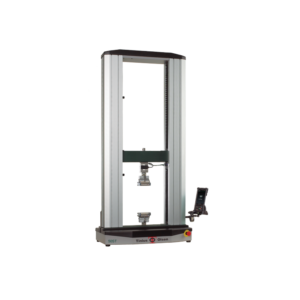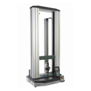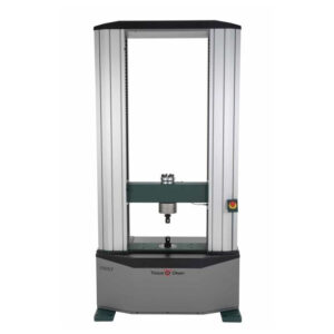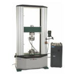
Electromechanical Universal Testing Machine Model 150 ST
A variety of loadcells are available at differing capacities that give precise applied load measurements from the smallest test specimen to ones that go to full machine capacity. Test machines become complete, powerful test systems with the addition of grips to hold the specimen, strain measurement instrumentation and Tinius Olsen’s Horizon software.
- Description
- Additional information
Description
HIGHLIGHTS
– Tinius olsen with a history of more than 140 years since 1880 in the field of Material Durability Testing.
– Install a single Horizon software on a computer that can be used for many different machines.
– Stable working ability, high durability and easy maintenance to help customers save costs.
– Library of test methods with at least common standards such as ASTM, ISO, EN, DIN, JIS, etc. Allows users to access relevant international standards or create new standards.
– Support to use Teamview Online technology during the time of using the software. Help technicians solve problems and problems in the process of using more effectively.
– The CEOs, Directors, and Engineers of Tinius Olsen Company participated in researching and developing a number of standards for testing material durability in the ASTM system of standards, which were published on the official website of the ASTM standards organization. .
– Easy to use: Allows testing and reporting in just 4 clicks.
1. Start the test.
Get Crosshead back.
Confirm the result
Print report.
| Value SI | ||
| 150ST | ||
| Tension Compression load capability | Yes | |
| Frame capacity | 150kN | |
| To frame capacity | |
| Floor or table mounting | Floor standing | |
| Test zones | 1 | |
| Number of columns | 2 | |
| Column material | Aluminium Extrusion | |
| Column finish | Anodise | |
| Column colour | Natural | |
| Base material | Mild Steel | |
| Base finish | Pre primed, top coat powder coat paint | |
| Base colour | TO Cool Grey Web # E6 30 27 | |
| Crosshead material | Mild Steel solid | |
| Croshead finish | Pre primed, top powder coat paint | |
| Crosshead colour | TO Green Web # 00 4C 45 | |
| Base cover | ABS recyclable | |
| Base cover colour | Cal Black Web # 11 18 20 | |
| Distance between columns | 656mm | |
| Max cross head travel | 1198mm | |
| Optional extension to cross head travel | 400mm | |
| Stiffness | 460kN/mm | |
| Height | 2323mm | |
| Width | 1205mm | |
| Depth | 700mm | |
| Weight | 954kg | |
| Force protection system | Yes digital | |
| Displacement protection system | Yes mechanical & user programmable | |
| Accessory fitting interface type | Female diameter | |
| Ball screw type | High precision low backlash | |
| Ball screw cover/protection | Yes | |
| Crosshead drive system | AC servo motor | |
| Feet material | Mild Steel with anchor bolt oprtion | |
| Feet adjustment & levelling | Yes provision for M20 jacking screw | |
| Reference rule to support cross head positioning | Yes | |
| T slots in columns for accessory mounting | 12 * M6/M8 | |
| Noise at full crosshead speed 2m radius | 42db |
| Spec parameter | Value SI | |
| Controller | Max data processing rate | 168 MHz |
| Data acquisition rate at PC | 1000 sps | |
| Number of instrument device connections external | 4 | |
| Number of instrument device connections internal | 3 | |
| Bluetooth enabled | v4.0 with A2DP, LE, EDR | |
| External PC connection | USB | |
| User interface connectivity | TO HMC, Proterm, Horizon | |
| Force | Force measuring device – type | Strain gauge based load cell |
| Load cells available | 5N, 10N, 25N 50N, 100N, 250N, 500N, 1kN | |
| Resolution | 1 part in 8,388,608 | |
| Accuracy | +/-0.1% of applied force across load cell force range | |
| Range | 0.2% to 100% | |
| Calibration standard | ISO 7500-1 ASTM E4 | |
| Internal sampling rate | 1000sps | |
| Extension measurement – xhead | Resolution | 0.1um |
| Accuracy | +/-10um | |
| Range | +/- 217m | |
| Calibration standard | ISO 9513, ASTM E83 | |
| Internal sampling rate | 2.73ksps | |
| Position control | Test Speed | 0.001mm/min to 1000 mm/min |
| Resolution | 0.1um | |
| Accuracy | +/- 0.005% | |
| Return speed post test | 0.001mm/min to 1500 mm/min | |
| Resolution | 0.1um | |
| Accuracy | +/- 0.005% | |
| Crosshead positioning speed | 0.001mm/min to 1500 mm/min | |
| Resolution | 0.1um | |
| Accuracy | +/- 0.005% | |
| Return to zero function | Yes | |
| Power requirement | Supply voltage options | 110/240V |
| Frequency | 50/60Hz | |
| Current | ||
| Power | 2000W +/- 10% | |
|
| ||
| Atmosphere | Operating temperature | 10 to 40 degree C |
| Operating humidity | 10% to 90% non condensing | |
| Storage temperature | 10 to69 degree C | |
| Storage humidity | 10% to 90% non condensing | |
The ST series of electromechanical testing machines from Tinius Olsen are designed to test a wide range of materials, including, but not limited to: plastics, films, paper, packaging materials, filter material, adhesives, foils, food, toys, medical devices and components, in tension, compression, flexure, shear, and peel.
1.Grip 67-N-24
These open front lever operated grips, known as “K” grips, have a positive, self-aligning gripping action and allow rapid sample insertion and removal. The grips are supplied as standard with flat file inserts, but solid or insert type vee wedges can be supplied for round specimens. At some capacities, Tinius Olsen offers a choice of wedge angle – one with an 8½° angle for maximum gripping pressure (recommended for hard, smooth faced materials) or one with a 15° angle for a wide range of sample types.
The suspended wedge tensile grips are used on ST and SL series materials testing machines.
Specifications
30kN/6,000lb grips
♦ Wedge Angle: 8½°
♦ Maximum Diameter (with vees): 12.7mm/0.5in
♦ Minimum Diameter (with vees): 6.35mm/0.25in
♦ Maximum Thickness (with flats): 8mm/0.3125in
♦ Maximum Width (with flats): 25mm/1in
♦ Gripping Length: 70mm/2.75in
♦ Weight Each: 5.9kg/13lb
60kN/12,000lb grips
♦ Wedge Angle: 8½°
♦ Maximum Diameter (with vees): 12mm/0.5in
♦ Minimum Diameter (with vees): 8mm/0.3125in
♦ Maximum Thickness (with flats): 9.5mm/0.375in
♦ Maximum Width (with flats): 44mm/1.75in
♦ Gripping Length: 70mm/2.75in
♦ Length Each: 184mm/7.25in
♦ Weight Each: 9kg/20lb
60kN/12,000lb grip
♦ Wedge Angle: 15°
♦ Maximum Diameter (with vees): 22mm/0.875in
♦ Minimum Diameter (with vees): 6.35mm/0.25in
♦ Maximum Thickness (with flats): 15mm/0.625in
♦ Maximum Width (with flats): 44mm/1.75in
♦ Gripping Length: 70mm/2.75in
♦ Length Each: 168mm/6.61in
♦ Weight Each: 9kg/20lb
150kN/30,000lb grips
♦ Wedge Angle: 15°
♦ Maximum Diameter (with vees) 28mm/1.125in
♦ Minimum Diameter (with vees): 8mm/0.3125in
♦ Maximum Thickness (with flats): 22mm/0.875in
♦ Maximum Width (with flats): 50mm/2in
♦ Gripping Length: 70mm/2.75in
♦ Length Each: 190mm/7.48in
♦ Weight Each: 16.3kg/36lb
60kN/12,000lb grips
♦ Wedge Angle: 15°
♦ Maximum Diameter (with vees) 22mm/0.875in
♦ Minimum Diameter (with vees): 6.35mm/0.25in
♦ Maximum Thickness (with flats): 15mm/0.625in
♦ Maximum Width (with flats): 44mm/1.75in
♦ Gripping Length: 70mm/2.75in
♦ Length Each: 168mm/6.61in
♦ Weight Each: 9kg/20lb
150kN/30,000lb grips
♦ Wedge Angle: 15°
♦ Maximum Diameter (with vees): 28mm/1.125in
♦ Minimum Diameter (with vees): 8mm/0.3125in
♦ Maximum Thickness (with flats): 22mm/0.875in
♦ Maximum Width (with flats): 50mm/2in
♦ Gripping Length: 70mm/2.75in
♦ Length Each: 190mm/7.48in
♦ Weight Each: 16.3kg/36lb
Applications
♦ Metals
♦ Other high strength materials
2.Grip 67-N-25
These grips use a spring tension closure to ensure a uniform gripping action – this is a particularly important feature for relatively fragile specimens. The type KR grips are normally supplied with flat wedges but wedges with the ability to accept round samples are available on special order.
Specifications
The suspended wedge tensile grip is used on ST and SL series materials testing machines.
500N/100lbf grips
♦ Wedge Angle: 15°
♦ Maximum Thickness (with flats): 6.35mm/0.25in
♦ Maximum Width (with flats): 25mm/1in
11kN/2,500lbf grips
♦ Wedge Angle: 15°
♦ Maximum Thickness (with flats): 9.5mm/0.38in
♦ Maximum Width (with flats): 31mm/1.25in
25kN/5,000lbf grips
♦ Wedge Angle: 15°
♦ Maximum Thickness (with flats): 9.5mm/0.38in
♦ Maximum Width (with flats): 31mm/1.25in
Applications
♦ Metals
♦ Other high strength materials
3.Grip 67-N-27
Used for testing standard threaded and headed specimens in accordance with ASTM E8. These holders are used in conjunction with two spherically seated plates and nuts with matching studs.
They are typically made for testing 0.505in diameter threaded specimens although adaptors are available to accommodate 0.357in or 0.252in diameter test bars or cast iron bars of 0.5in, 0.75in or 1.25in diameter.
Additionally, split adaptors for headed specimens can be supplied in various sizes and metric versions are also available for both headed and threaded holders.
The suspended tensile grips are for use on SL series materials testing machines.
Specifications
♦ Maximum Force: 150kN/30,000lbf
♦ Length Each: 40mm/1.6in
♦ Weight Each: 150g/0.33lb
Applications
♦ Metals
♦ Other high strength materials
4.Grip 67-N-38
Designed for testing wire rope, flexible cable, rope and similar items up to 3/8in (9.5mm) diameter. The sample is wrapped around the 4.5in (114mm) diameter grooved spools with its end securely held between the split spools by action of the integral clamping bolts.
The suspended tensile grip is used on SL series materials testing machines.
Specifications
♦ Maximum Capacity: 66kN/15,000lbf
♦ Maximum Diameter: 9.5mm/0.375in
Applications
♦ Rope
♦ Wire
♦ Cable
♦ Other high strength flexible materials
5.Grip 67-N-39
Designed for testing fabric, webbing, strapping and similar materials. The sample is wrapped around the 2in (50mm) diameter smooth spools with its end securely held between the serrated faces of the split spools.
The suspended tensile grip is used on ST and SL series materials
testing machines.
Specifications
♦ Maximum Capacity: 11kN/5,000lbf
♦ Maximum Width: 23mm/0.9in
♦ Maximum Thickness: 7.6mm/0.3in
Applications
♦ Fabric
♦ Webbing
♦ Strapping
♦ Other similar flexible flat material
6.Grip 67-N-42
Originally developed in the USAF Wright Field Lab for testing parachute webbing, these Sedam grips are made in several capacities.
Specifications
The suspended tensile grip is used on ST and SL series materials testing machines.
Maximum Capacity: 11kN/5,000lbf
Maximum Width: 101.6 mm/ 4.0 in
Maximum Thickness: 7.6mm/0.3in
Maximum Capacity: 50kN/12,000lbf
Maximum Width: 152.4 mm/ 6.0 in
Maximum Thickness: 9.5mm/0.375in
Maximum Capacity: 150kN/30,000lbf
Maximum Width: 152.4 mm/ 6.0 in
Maximum Thickness: 7.6mm/0.3in
Maximum Capacity: 300kN/60,000lbf
Maximum Width: 152.4 mm/ 6.0 in
Maximum Thickness: 7.6 mm/0.3in
Maximum Capacity: 1,000kN/200,000lbf
Maximum Width: 330 mm/ 13.0 in
Maximum Thickness: 7.6 mm/0.3in
Applications
♦ Fabric
♦ Webbing
♦ Strapping
♦ Other similar flexible flat material
7.Grip 67-N-91
Used for rapid testing standard headed specimens in accordance with ASTM E8, A370 and B557. The sample is inserted into the two pairs of split sockets and the outer clamping ring slides down over them to lock the sample in place.
The suspended tensile grips are used on ST and SL series materials testing machines.
Specifications
For testing 0.505in specimens
♦ Maximum Force: 200kN/40,000lbf
♦ Length Each: 40mm/1.6in
♦ Weight Each: 150g/0.33lb
For testing 0.357in specimens
♦ Maximum Force: 100kN/20,000lbf
♦ Length Each: 40mm/1.6in
♦ Weight Each: 150g/0.33lb
For testing 0.252in specimens
♦ Maximum Force: 50kN/10,000lbf
♦ Length Each: 40mm/1.6in
♦ Weight Each: 150g/0.33lb
Applications
♦ Metals
♦ Other high strength materials
8.Grip 67-N-93
Unique spherically seated design of all Tinius Olsen stud mounted grips ensures positive alignment.
Automatic self-alignment is obtained by the free movement of a spherical nut in a matching spherical counter-sink in the mounting plate. When the sample fails, shock and grip recoil is absorbed by the helical spring.
Specifications
♦ Length Each: 40mm/1.6in
♦ Weight Each: 150g/0.33lb
Applications
The suspended tensile grip is for use on SL series materials testing machines.
9.Hydraulic Tensile Grip 01036010
These side loading hydraulic wedge grips (ref. 01036010) are used on high force electromechanical test frames and hydraulic test frames.
Specifications
♦ Maximum Capacity: 120kN/30klbf
♦ Standard Wedge Width: 45mm/1.75in*
♦ Length Each: 180mm/7.4in
♦ Weight Each: 30kg/67lb
♦ Temperature Limits: -40 to 175°C
♦ Required Hydraulic Pressure: 21MPa/3kpsi
*Alternate wedge widths available
Required accessories (see below)
Applications
♦ Metal
♦ Other high force specimens
Hydraulic pumping unit
with grip control for use with the 120kN grips (ref. 01036010).
Specifications
♦ Maximum Pressure: 21MPa/3kpsi
♦ Minimum Pressure: 0.7MPa/100psi
♦ Pressure Stability: +/-100psi
♦ Weight: 76kg/170lb
♦ Temperature Range: -40 to 177
Alignment Fixture (ref. 01036003)
Alignment Fixture (ref. 01036003)
This allows alignment adjustment to eliminate loading inconsistencies and inaccuracies that frequently occur during sample loading.
It has a maximum capacity of 120kN/30klbf.
11.Wedge Grip Faces
These are used in the side loading hydraulic wedge grip body and are available in a variety of different shapes that best match the specimen profile.
Flat Wedge Specimens
Specimen Thickness:
0-7.6mm/0-0.3in
7.1-14.2mm/ 0.28-0.56in
11.7-19.1mm/ 0.46-0.75in
Narrow Wedge Set
Wedge Width: 44.5mm /1.75in
Wide Wedge Set
Wedge Width: 76.2mm/3.00in
Round Wedge Specimens
Specimen Diameter: 12,15,20mm/0.5,0.75,1.0in
Vee Wedge Specimens
Specimen Diameter:
5.8-10.2mm/0.23-0.40in
10.9-12.8mm/0.43-0.5in
12.R Grip
These grips use a unique balanced design that allows easy insertion of the specimen into these open front grips without bowing or bending the sample. Two types of actuation are available: a spring activated lever that allows faster insertion and removal of the sample, or a rotary type that moves the wedges horizontally when the handles are turned that maintains positive gripping without any vertical motion, eliminating any sample buckling.
The suspended wedge tensile grip is used on ST and SL series materials testing machines.
Specifications
60kN/12,000lbf grips
♦ Wedge Angle: 15°
♦ Maximum Thickness (with flats): 15mm/0.625in
♦ Maximum Width (with flats): 44mm/1.75in
♦ Maximum Diameter (with vees): 19mm/0.75in
♦ Minimum Diameter (with vees): 8mm/0.3125in
♦ Gripping length: 70mm/2.75in
♦ Length Each: 193mm/7.6in
♦ Weight Each: 6.7kg/14.8lb
150kN/30,000lbf grips
♦ Wedge Angle: 15°
♦ Maximum Thickness (with flats): 25mm/1in
♦ Maximum Width (with flats): 50mm/2in
♦ Maximum Diameter (with vees): 25mm/1in
♦ Minimum Diameter (with vees): 6.35mm/0.25in
♦ Gripping Length: 70mm/2.75in
♦ Length Each: 210mm/8.27in
♦ Weig
ht Each: 15.7kg/34.7lb
Applications
♦ Metals
♦ Other high strength materials
13.VEM 100 Series
Tinius Olsen’s VEM 100 series of video extensometer modules are designed to measure higher levels of strain (>10%) in tensile, compression, shear and flexural modes.
The units are fully integrated with the testing machine and results-reporting software, supporting multiple gauge length click and drag placements, strain rate control and real time results during and throughout the test.
The VEM 100 series is directly compatible with all Tinius Olsen testing machine frames. It is mounted using a stabilised carbon fibre arm with built-in X, Y and Z fine positioning adjustment for optimum measuring performance.
The unit can be mounted at the front or rear of a testing machine, left or right in support of operator comfort and efficiency of use. The extensometer on its mounting arm can be quickly moved away from the test area, ensuring full operator access for specimen loading and grip or accessory changes, then equally quickly swung back into position, locating precisely using the magnetic homing position – simple, precise and quick.
The built-in lighting strip ensures repeatability in tests irrespective of lab conditions yet requires no special light sources or red colours, being easily controlled by the user adjusting intensity as required to ensure a stable light environment.
Information
These versatile extensometer modules are available in a number of different performance configurations each compatible with Tinius Olsen’s Horizon and VSS materials testing software, whether the Basic, Standard or Advanced option.
The precise camera, lens and data acquisition technology delivers zero gauge length error every time and quick application of gauge marks, including for the measurement of rotation (to track specimen alignment) during testing. Calibration is digitally embedded but, for reassurance, can be checked at any time using the standard traceable gauge block supplied.
For most applications a single VEM extensometer module meets the need, but up to four extensometer modules can be synchronised to work together capturing four simultaneous events.
The VEM Video Extensometer is the future of extensometery simply because it improves productivity through speed of use, improves repeatability and aids traceability via the embedded strain data video stored as part of the results data set. In addition, there are no mechanical parts under strain when subjected to the release force at the specimen break point.
Key Features
♦ Non-contacting video extensometer solution
♦ One extensometer measures in tension, compression, flexural, shear modes
♦ No risk of damage due to violent specimen breaks
♦ Capable of measuring up to 1000% strain
♦ Supports quick gauge length change 10mm, 25mm, 50mm, 100mm, 200mm
♦ Provides a permanent record for recall of the test in video format with full resolution embedded strain data
♦ Meets the requirements of ISO 9513 class 0.5, ASTM E83 class B1 and GB/T 12160 class 0.5
14.VEM 200 Series
Tinius Olsen’s VEM 200 series of video extensometer modules is designed to measure low levels of strain from 0.01% in tensile, compression, shear and flexural modes.
The units are fully integrated with the testing machine and results-reporting software, supporting multiple gauge length click and drag placements, strain rate control and real time results during and throughout the test.
The VEM 200 series is directly compatible with all Tinius Olsen testing machine frames. It is mounted using a stabilised carbon fibre arm with built-in X, Y and Z fine positioning adjustment for optimum measuring performance.
The unit can be mounted at the front or rear of a testing machine, left or right in support of operator comfort and efficiency of use. The extensometer on its mounting arm can be quickly moved away from the test area, ensuring full operator access for specimen loading and grip or accessory changes, then equally quickly swung back into position, locating precisely using the magnetic homing position – simple, precise and quick.
The built-in lighting strip ensures repeatability in tests irrespective of lab conditions yet requires no special light sources or red colours, being easily controlled by the user adjusting intensity as required to ensure a stable light environment.
Information
These versatile extensometer modules are available in a number of different performance configurations each compatible with Tinius Olsen’s Horizon and VSS materials testing software, whether the Basic, Standard or Advanced option.
The precise camera, lens and data acquisition technology delivers zero gauge length error every time and quick application of gauge marks, including for the measurement of rotation (to track specimen alignment) during testing. Calibration is digitally embedded but, for reassurance, can be checked at any time using the standard traceable gauge block supplied.
For most applications a single VEM extensometer
module meets the need, but up to four extensometer modules can be synchronised to work together capturing four simultaneous events.
The VEM Video Extensometer is the future of extensometery simply because it improves productivity through speed of use, improves repeatability and aids traceability via the embedded strain data video stored as part of the results data set. In addition, there are no mechanical parts under strain when subjected to the release force at the specimen break point.
Key Features
♦ Non-contacting video extensometer solution
♦ One extensometer measures in tension, compression, flexural, shear modes
♦ No need for bonded strain gauges or multiple clip on extensometers for r&n
♦ Supports axial, transverse, orthogonal and rotational measurements
♦ Provides a permanent record for recall of the test in video format with full resolution embedded strain data
♦ Meets the requirements of ISO 9513 class 0.5, ASTM E83 class B1 and GB/T 12160 class 0.5
15.VEM 300 Series
Tinius Olsen’s VEM 300 series Video extensometer is designed as a flexible platform allowing users to define their own extensometer performance using standard technology building blocks these being to measure low or high strain in tensile, compression, shear and flexural modes. The building blocks consist of camera and lens, lighting, machine frame mounting options and data exchange options.
The VEM 300 series is directly compatible with all Tinius Olsen testing machine frames, single, twin and four column machines, camera staging options are available including a unit that allows for fine X, Y and Z camera positioning and adjustment for optimum measuring performance. The 300 series can be mounted at the front or rear of most testing machines or free standing on a tripod.
There are over 70 lens types to choose from in pursuit of a specific camera lens performance, be it data capture speed, field of view in which the event will occur, resolution and accuracy.
Information
This versatile extensometer platform delivers zero gauge length error every time, quick application of gauge marks including for the measurement of rotation to track specimen alignment during the test. Calibration is digitally and can be verified at any time using a standard traceable gauge block supplied.
Tinius Olsen’s VEM Video extensometer is the future of extensometery simply because it is straight forward to use be it in a research application or as an educational tool. Test reporting is strengthened by the strain embedded video record which along with the strain mapping option gives depth to material analysis and reports.
Key Features
♦ Non-contacting video extensometer solution
♦ System supports up to four synchronised cameras capturing data real time and simultaneously
♦ Measures in tension, compression, flexural, shear modes
♦ No need for bonded strain gauges or multiple clip on extensometers for r&n
♦ Supports axial, transverse, orthogonal and rotational measurements
♦ Provides a permanent record for recall of the test in video format with full resolution embedded strain data
♦ Meets the requirements of ISO 9513 class 0.5, ASTM E83 class B1 and GB/T 12160 class 0.5 proportional low strain
Automatic Extensometer
The extensometer models AE300 and AE500 are suitable for almost all samples with an initial gauge length from 10mm. Their low clamping forces combined with high measurement accuracy makes them highly suitable even for small, notch sensitive test samples.
The AE series can be connected to partly or fully automatic testing machines and used with all types of grips. The strain can be measured from the elastic range to fracture for almost all types of samples. When used in combination with the transverse models, the AE extensometers are highly suitable for testing the deep-drawing properties of thin sheets.
The AE extensometers are controlled through Tinius Olsen’s Horizon software via a serial interface (RS232 or USB). All movements can be initiated at any time required. The measuring arms can be positioned in parallel within the available interval under computer control and thus can quickly be adjusted symmetrically to different sample lengths.
Specifications
♦ Accuracy class EN ISO 9513: 0.5
♦ Accuracy class ASTM E83: B1
♦ Measurement principle: opto-incremental
♦ Travel (minus gauge length): 300mm (AE 300)/500mm (AE 500)
♦ Position travel: 190mm
♦ Gauge length: 10 to 300mm (AE 300)/10 to 500mm (AE 500)
♦ Indication error (rel.): 0.5%*
♦ Indication error: 1.5µm*
♦ Error in linearity: 0.005
♦ % error in gauge length: 0.5%
♦ Resolution: 1 or 0.1µm
♦ Activating force: <0.01N
♦ Clamping force: 0.25N**
♦ Operating temperature range: 0-50°C
♦ Weight: approx. 26kg (AE 300)/approx. 31kg (AE 500)
* The larger of the values is admissible
** The clamping force can be adjusted by tension springs
Key Features
♦ Two-sided measurement by means of four measuring sensors
♦ Very high resolution of up to 0.1μm over the complete measuring range
♦ Very low clamping forces even allow testing of foils and thin wires
♦ The round knife edges can be utilised along their entire perimeter by rotating them
♦ The gauge length position and value can be exactly set under computer control
LVDT Type Extensometer
Extensometers measure strain, the change in length of a specimen divided by the original length (gauge length) of the specimen, by means of knife edges that contact the sample, one of which is fixed in position and the other located on a moveable arm.
On these models, the moveable arm is pivoted – the knife edge is at one end and the other end is attached to an armature that moves through an LVDT coil.
Most of these extensometers can be adapted to exact specimen holding needs by the options that are described below, but in their standard form hold flat or round specimens from 1.6 to 16mm (1/16 to 5/8in).
Options 1
♦ Averaging — With this type of extensometer, knife edges are placed on opposite sides of the specimen to provide an average amount of strain between the two gauge points.
♦ Film Clamps — These spring activated clamps allow precise strain measurement of thin materials up to 3mm/0.125in thick, including plastics and foils, without marring the specimen. This option is only available for non-averaging extensometers and typically requires the use of a counterbalance to support the extensometer.
♦ Breakaway Release — This option is ideal for measuring strain on samples with brittle characteristics that may cause premature failure. It typically requires the use of a counterbalance to support the extensometer and is available for both averaging and non-averaging type extensometers.
♦ Sheet Metal Attachment — This option allows the extensometer to accommodate thin, flat specimens. Note that this option is only available for non-averaging extensometers and typically requires the use of a counterbalance to support the extensometer.
Options 2
♦ Extension Bracket — This option allows the extensometer to be used with samples that are thicker than maximum opening of 16mm/0.625in on the standard model. There are three versions where an extension bracket allows the extensometer to be mounted on samples that are 25mm/1in, 50mm/2in or 75mm/3in thick. This option is only available for non-averaging extensometers.
♦ Pneumatic Release — This option is combined with a swing-away support and allows the remote release of the extensometer from the sample.
♦ Counterbalance Support – This option is used to support the extensometer and is commonly used when the extensometer is attached to small or fragile samples.
16.Model 100R Extensometer
The Tinius Olsen model 100R is a high elongation extensometer that is designed to measure the ‘stretch’ of a wide range of materials including elastomers and non-rigid plastics.
The initial measuring length, or gauge length, can be changed to suit the specimen size or the test standard that is being applied.
The unique design ensures an extremely low tracking force for testing sensitive materials, as well as a robust construction that can easily withstand the high release forces and breaking energies with certain specimens.
The design also incorporates a simple yet effective method by which the extensometer followers are attached to the specimen, allowing rapid throughput of testing.
Specifications
♦ Elongation Measurement Range: 720mm/28.35in (extended options available)
♦ Gauge lengths: 10, 15, 20, 25, 40 50mm
♦ Accuracy: 1% on 25mm gauge length, ISO 5893 class A, ASTM E83 class C
♦ Resolution: 0.01mm/0.0004in
♦ Tracking Force: <10g/<0.02lbf
♦ Specimen Thickness: 0 to 5mm/0 to 0.2in
♦ Dimensions: H x W x D 1015 x 53 x 200mm/40 x 2.1 x 7.9in
♦ Weight: 5.5kg/11lb
17.Measuring Extension
Extension is measured by attaching two counterbalanced extensometer clamps to the specimen at a pre-selected gauge length. When tensile forces are applied to the specimen by the testing machine, the slightest change in gauge length is measured by an optical encoder. Signals from the optical encoder are fed into the signal conditioner interface for processing.
The 100R extensometer can be fitted to all sizes of screw-driven materials testing machines.
18.Model 100S Extensometer
The Tinius Olsen model 100S is designed as a dual purpose extensometer to measure E modulus and offset yield stress (proof stress) on relatively high modulus materials while also providing the ability to measure high elongations up to break.
A typical application is the testing of polycarbonate, where a high resolution system is required to measure the E modulus (Youngs modulus) and a secondary system is required to measure elongation to the point of break, which typically could be as high as 200% strain.
Other materials the 100S extensometer is ideally suited to include polyurethane, polyethylene (PET), glass reinforced plastics (GRP), and aluminum alloys.
The unique design ensures an extremely low tracking force for testing sensitive materials
and a construction that is sufficiently robust to withstand the release force when the specimen breaks. An important feature is the ease with which the extensometer clamps can be attached to the specimen, resulting in very rapid testing throughput.
Specifications
Range of Scan:
♦ LVDT Transducer – 10% on 25mm/1in gauge length, 5% on 50mm gauge
♦ Optical Digital Encoder – 720mm/28.35mm (extended options available)
Accuracy:
♦ LVDT Transducer – 1%, EN10002-4 Class 1
♦ Optical Digital Encoder – 1% on 25mm gauge length, BS5214 grade C&D
Resolution:
♦ LVDT Transducer – 0.0005mm/0.00002in
♦ Optical Digital Encoder – 0.0004mm/0.01in
♦ Tracking force – 10g/0.02lbf
♦ Specimen Thickness – 0 to 10mm/0 to 0.4in
♦ Dimensions: H x W x D 1015 x 95 x 200mm/40 x 3.75 x 7.9in
♦ Weight: 7.5kg/16.5lb
19.Measuring Extension
Extension is measured by attaching two counterbalanced extensometer clamps to the specimen at a preselected gauge length.
When tensile forces are applied to the specimen by the testing machine, the slightest change in gauge length is measured by a precise LVDT transducer. If the range of this LVDT transducer is exceeded, measurement of elongation and strain transfers to an optical encoder.
Signals from the LVDT and optical encoder are fed into the signal conditioner interface for processing. The 100S extensometer can be fitted to all twin-screw materials testing machines and must be used under software control.
20.Model 500LC Laser Extensometer
The Tinius Olsen model 500LC non-contacting extensometer is designed to measure the extension of medium to high elongation materials, typically elastomers. Since there is no contact between the extensometer and the sample, the 500LC is also ideal for measuring the elongation of fragile samples where such contact could induce a premature sample break.
The model 500LC uses a low power helium neon laser with precision optical components and a dedicated 16-bit processor. The laser projects a visible red scanning beam that is directed at two reflective targets attached to the specimen.
An additional benefit of using laser technology is its ability to scan the test specimen through the glass viewing window of an environmental test chamber. Elongation characteristics can then be evaluated from –70°C to 300°C.
Specifications
♦ Range of Measurement: Up to 600mm/23.6in
♦ Gauge Lengths: 10mm/0.39in to full scan
♦ Accuracy: 1% on 25mm gauge length, BS5214 grade D
♦ Resolution: 0.012mm/ 0.000472in with filtering
♦ Optical Scan: 320 scans per second/90 degrees
♦ Dimensions: H x W x D 320 x 111 x 180mm/ 32 x 4.4 x 7.9in
♦ Weight: 7kg/15.5lb
21.Measuring Extension
Preparation of the test specimen is quick and easy. A punch is supplied to cut narrow strips of adhesive reflective tape. The gauge length is defined by attaching these two reflective strips to the sample. Any gauge length can be used and this is accurately measured by the laser at the start of the test. When force is applied to the sample, the laser scanning beam will measure the separation of the reflective gauge marks at a scan rate of 320 scans per second.
Unlike other non-contacting extensometers, if the scanning beam is interrupted for any reason, elongation measurements will automatically be corrected when normal operation is resumed.
22.Non-Contact Video Extensometer
Tinius Olsen’s Epsilon ONE high-precision optical extensometers measure axial strain with industry-leading resolution, accuracy and speed.
Innovative Instant Reset, Always On and Laser Alignment features maximize performance and increase testing throughput.
Tinius Olsen Epsilon ONE optical non-contact extensometers perform high-accuracy, high-resolution, non-contacting axial strain and displacement measurement. These extensometers are suitable for testing high-modulus materials such as metals and composites, high-elongation materials, thin or delicate specimens, cyclic fatigue, strain controlled testing, deflectometer applications, and measuring crack opening displacements. Strain or extension is measured and output in real time.
Epsilon ONE’s high resolution and ISO 0,5 / ASTM B-1 accuracy classes make it suitable for non-contact measurement of a wide range of strain values, from very small strains required to measure modulus of metals, composites, ceramics and CMCs through elastomers and everything in between.
Information
Class-leading accuracy and resolution are achieved by Epsilon’s comprehensive optical path optimization, a unification of several optical technologies and signal processing algorithms. Ultra-high camera resolution, real-time data rates up to 3000Hz, minimization of optical error sources, and signal processing techniques provide high strain resolution and accuracy with the lowest noise. No other system on the market combines all of these technologies.
The Laser-Assist Alignment System provides an instant alignment and distance spot check. Epsilon ONE will project pre-aligned laser lines on the specimen befor
e the test, revealing any misalignment. During the test, high precision telecentric lenses eliminate errors due to out-of-plane movements – on low strain materials and components. Epsilon ONE arrives factory calibrated – there are no calibration grids or gauge length bars, saving a great deal of time.
The system sets up for new specimen types in minutes and requires very little training or skill to use. The desktop user interface software and optional Touch Interface provide continuous digital readouts and status information. Epsilon ONE was designed for the fastest specimen cycle times. Auto-start repetitive tests without any software interaction; Epsilon ONE is always running, and its Instant Reset and Automatic Mark Detection eliminate software start/stop interactions common with video extensometers. Epsilon ONE fits all types of materials testing machines. The system may be used with environmental chambers that are equipped with a window
Key Features
♦ Non-contacting video extensometer solution
♦ Resolution, accuracy and speed
♦ Always on, always real time
♦ Telecentric design
♦ Laser assist alignment system
♦ Real-time digital output
♦ Better strain control
♦ Applicable for testing with many ISO, ASTM standards
♦ ISO 6892-1, 527-2, 527-4, 527-5
♦ ASTM E8, E9, D3039, D638, A370, D3552, E646
23.Strain Gauge Type Extensometers
Extensometers measure strain, the change in length of a specimen divided by the original length (gauge length) of the specimen, by means of knife edges that contact the sample. This series of extensometers comprises strain gauged devices.
Specifications
The models in this series of extensometer can be used to measure either longitudinal or transverse strain, or can be used in combination for determining ‘r’-value and Poisson’s ratio.
SGM Models – Metric Units: Measuring Range, Gauge Length, Direction
♦ SGM-20%-50: 20%, 50mm, Longitudinal
♦ SGM-20%-25: 20%, 25mm, Longitudinal
♦ SGM-20%-80: 20%, 80mm, Longitudinal
♦ SGM-50%-80: 50%, 80mm, Longitudinal
♦ SGM-50%-50: 50%, 50mm, Longitudinal
♦ SGM-100%-50: 100%, 50mm, Longitudinal
♦ SGMT-10%-25: +/-2.5mm, 0-25mm,Transverse
SG Models – English Units: Measuring Range, Gauge Length, Direction
♦ SG-20%-2: 20%, 2in, Longitudinal
♦ SG-20%-1.4: 20%, 1.4in, Longitudinal
♦ SG-20%-1: 20%, 1in, Longitudinal
♦ SG-20%-0.5: 20%, 0.5in, Longitudinal
♦ SG-50%-2: 50%, 2in, Longitudinal
♦ SGT-10%-1: +/- 0.1in, 0 to 1in, Transverse
Key Features
♦ Can be left on specimen through failure
♦ Lightweight to minimise any influence on the test
♦ Low operating force
♦ Rugged construction to withstand rigours of operation
Horizon Software
Computer assisted data acquisition and machine control system which can be supplied with most Tinius Olsen testing equipment. The Horizon software package allows data to be collected, analyzed, graphed (where appropriate), and stored. If the testing machine allows, it can also provide control over testing operations.
Horizon has a comprehensive selection of pre-defined testing programs which includes powerful analysis of testing data, complex control, and sophisticated reporting. These programs can be modified and further enhanced to fit a customer’s particular requirements. The testing data collected by these programs may be exported to an outside source then later transferred to other data analysis systems. The Horizon databases may also be configured to be shared across several computers on a company’s network thereby allowing the testing programs and testing data to be utilized by multiple systems.
Using Horizon will make easy work of your materials testing, whether it’s designed for the demanding rigors of R&D or the charting and analysis functions of QC testing.
Key Features Overview
| Advanced Machine Segment Control |
| Customizable Report Layout |
| Data Archiving and Backup |
| Data Exporting (Results/Limits/Statistics/Points) |
| Data Importing (Result Entries/Limits) |
| Data Stored with SQL Server Express |
| Formula Generation |
| Library of Pre-Defined Testing Programs |
| Method/Output Editor |
| Multiple Graphs/Reports for Output |
| Multiple Machine Controlled by one Horizon |
| Multiple Users |
| Networking Databases |
| Report Consolidation |
| RS232 Device Communication |
| Security Lockout Capability |
| Touchscreen Capability |
| Video Extensometer Capability |
Test & Recall
The testing area allows for the viewing of live data from the machine while the test is being performed. Multiple tabs showcase the recalling of previous testing data as well as each testing machine connected to the software. Once a testing tab is created, it never has to be destroyed. When a new testing program needs to be run, simply change the Tab Options and load a new program. Each testing tab can be configured to display custom results, multiple graphs, multiple plots on a single graph, and live data (including custom formulas). Each tab may be customized to suite a user’s preferences.
Method/Output Editor
The testing program transferred from the Library may be customized for the customer in the Method and Output Editors. Create custom batch/sample identifiers for reporting and recalling purposes. Enhance the control of the machine with advanced machine segments. Automatically accept tests then print or email the report based on pre-defined limits. Customize multiple reports for various recipients. Import specimen data (such as dimensions or limits) from an outside file based on an identifier. Export results, limits, statistics, and/or curve points to an external file.
Custom Results
Methods transferred from the Library contain a number of results which have been standardized. In the Result Editor, however, custom result can be created. Such results can might be defined as entry type, a single point along a curve, a calculation between two points along a curve, a live source, or even a calculated formula. Depending upon how the result is created, it can be added to a testing panel to be viewed during the test or added to a report.
Library of Methods
A searchable database containing a variety of pre-defined testing routines. These methods are based on Standards from ASTM, ISO, EN, BS, DIN and many more. These routines include testing in tension, compression, flexure, torsion, melt index, heat distortion, hardness, impact, and more. Each method may be transferred into the user’s main database and customized with their own identifiers, units, report layouts, etc. With each new version update of Horizon, more and more routines are added to the Library.
Help Desk
Access to the tutorials which guide a user is various activities in the software.Displays details of the Software Key including items purchased. System Information displays valuable data regarding the software as well as the computer which it is installed upon. This guides the Tinius Olsen support staff when there are questions regarding system functionality. Please also note this page offers quick access to the Horizon QS program which will allow our Tinius Olsen support staff to take control of the computer when assistance is requested.
Additional information
| Manufacturer | Tinius Olsen |
|---|---|
| Origin | USA |
| Type | Manual |