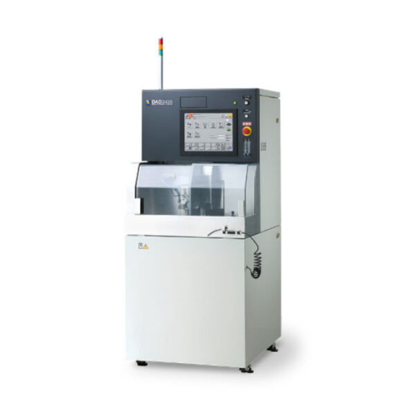
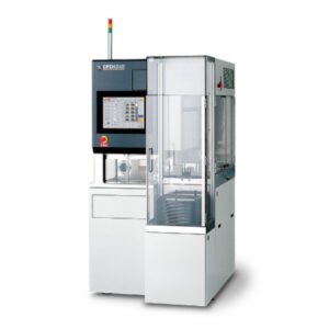
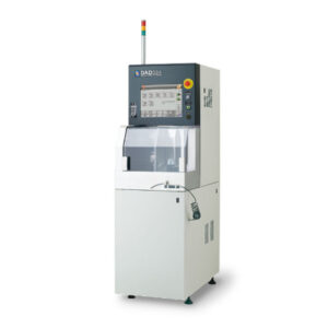
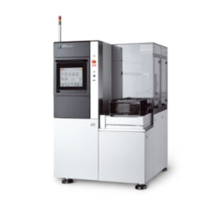
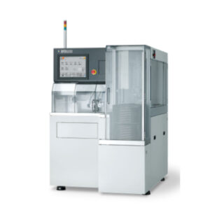
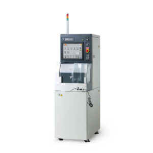
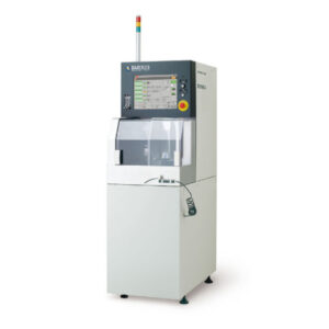
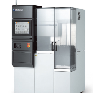
Automatic Dicing Saw DAD3430
Φ6-inch Compact Dicing Saw Which Achieves High-Precision, High-Quality Processing
Max. workpiece size Φ150 mm
Single spindle
- Description
- Additional information
Description
HIGHLIGHTS
Single-axis dicing saw which is compatible with the 6 x 6-inch workpiece using a user-specified specification.
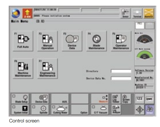
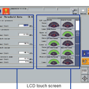
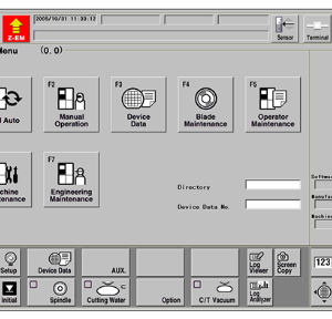
Each model features an LCD touch panel with a graphical user interface for easy and intuitive operation
The newly developed 1.5 kW spindle, which is standard on every model, features a shaft lock function for easier blade changing
A reduced-expansion spindle (option) manufactured with special expansion-resistant materials is available for even greater precision during processing.
| Specifications | unit | ||
| Max. workpiece size | Φ6 inch / 150 × 150 mm(user-specified specification) | ||
| X-axis | Cutting range | mm | 160 |
| Cutting speed | mm/s | 0.1 – 500 | |
| Y-axis | Cutting range | mm | 162 |
| Index step | mm | 0.0001 | |
| Index positioning accuracy | mm | 0.005/160 (Single error) 0.003/5 | |
| Z-axis | Max. stroke | mm | 32.2 (Φ2 inch blades) |
| Moving resolution | mm | 0.00005 | |
| Repeatability accuracy | mm | 0.001 | |
| θ-axis | Max. rotating angle | deg | 320 |
| Spindle | Output | kW | 1.5 |
| Rated torque | N.m | 0.48 | |
| Revolution speed range | min‐1 | 3,000 – 40,000 | |
| Microscope section (alignment) | System | Pattern matching system based on the target patterns from the CCD camera | |
| Scope | 0.64 mm square | ||
| Magnification | ・7.5x (pixel size: 0.0013 mm) | ||
| Direct light (LED) + Ring light (LED)[optional accessory] | Ring light provides workpieces with 360 degree illumination to deal with various workpiece surface conditions and kerf angle after cut | ||
| Kerf check | ・Compensation on a hairline standard ・Kerf width max./min. ・Check setting of random locations ・Check setting for each cut line number | ||
| Automatic light intensity adjustment | |||
| Auto focus | |||
| Auto alignment | |||
| Device type change | Alignment conditions can be switched autodevice data are changed | ||
| Alignment accuracy | ± 0.0013 mm | ||
| Alignment capable die size | 0.4 mm or more | ||
DAD3220 has a width of only 500 mm and was designed to be compact. The footprint is reduced approx. 14% compared to the existing model (DAD321).
The cutting water flow rate controller, programmable for each device data, helps prevent operator error while providing a stable and consistent flow of cutting water.
The macro microscope allows for a greater field of view and can improve usability during alignment.
A transformer and UPS can be installed on the equipment with consideration for the layout of peripheral units
| Power supply | 200 ~ 240 V AC±10 %, 3-phase (50/60 Hz) |
| Power consumption | When processing 0.5 kW (for reference) and During warm-up 0.4 kW (for reference) |
| Max power | 3.5 kVA |
| Air pressure | 0,5 ~ 0,8 MPa |
| Air max consumption | 200 L / min (ANR) |
| Clean air pressure | 0,5 ~ 0,8 MPa |
| Clean air max. consumption | 162 L / min (ANR) |
| Pressure water cutting | 0,2 ~ 0,4 MPa |
| Max. flow rate Cutting water | 0.2 ~ 4.0 L / min |
| Pressure cooling water | 0,2 ~ 0,4 Mpa |
| Flow rate cooling water | 1.5 at 0.3 MPa L / min |
| Exhaust duct capacity | 2.5 m3 / min |
| Machine dimensions(W x D x H) | 730 x 900 x 1,670 mm |
| Machine weight | Approx.600 kg |
| – semiconductor and electrical components manufacturer |
| – used in dicing and performs the cutting of the silicon wafer |
| Specification Selection | Specifications (Size) | Qty | |
| Fuse set (Glass) | 3.15A 250V | 1 | |
| USB memory | With machine data 2GB | 1 | |
| LED light | Maximum rated current: 27mA | 1 | |
| Halogen lamp | 7.5V 50W | 1 | |
| Universal chuck table | 6-inch | 1 | |
| Torque screwdriver | 400cN・m | 1 | |
| Bit | 1 | ||
| Duct cuffs | 32 75 | 2 2 | |
| Duct hoses | 32.0 I.D. 2 m 76.4 I.D. 2 m | 1 1 | |
| Pipe band | 32-35 77-85 | 2 2 | |
| Carbon brush | For 1.5kW spindle | 2 | |
| Locating pin | For chuck table | 1 | |
| Axis metal fixture | For X-axis For Y-axis For Z-axis | 1 set | |
| Wheel cover | For 1.5kW spindle Centrifugal type (resin) | 1 | |
| Flange specification selection | Hub specifications | Hub blade demounting jig | 1 |
| Wheel mount set for hub | 1 | ||
| Flange dressing jig set | 1 | ||
| Mounted flange dressing chip | 1 set | ||
| Wheel mount extraction jig set | 1 | ||
| R-type flange specifications | 48.2 × 40.0 | 1 | |
| 49.4 × 40.0 | 1 | ||
| 50.6 × 40.0 | 1 | ||
| 52.0 × 40.0 | 1 | ||
| 54.0 × 40.0 | 1 | ||
| Flange A extraction jig set ・Flange dressing jig set ・Flange dressing chip ・Flange B removal jig set ・The left items are contained with the above flange part no. as the set. ・The dresser board is not included with shipment. The dresser board varies depending on the blade type used. If you need the dresser board, consult your DISCO sales representative. | |||
| Attached manual selection | Japanese manuals | Safety Manual Installation Manual Operation Manual Data Maintenance Manual Maintenance Manual Technical Reference | 1 |
| English manuals | 1 | ||
| Label selection: The languages used for the labels on the machine outer cover | Japanese English German French Italian Chinese (Simplified) Chinese (Traditional) Portuguese Korean | ・Rotating blade ・Moving parts ・Hot surface ・Hazardous voltage ・Line voltage always present | 1 |
| Tape Frame | ||
| Cassette | ||
| Low-expansion spindle | ||
| 2-inch Hub Mount Spare (For 1.5kW Spindle) | ||
| 2-inch Hub Mount Jig (Spare) | ||
| R-type Flange Spare (For 1.5kW Spindle ) | ||
| R-type Flange Jig (Spare) | ||
| Chuck Table for Tape Cutting | ||
| Maintenance Parts Kit | ||
| General Tool | ||
| Advanced Tool | ||
| Lifting Jig Set | ||
| Axis Metal Fixture (Spare) | ||
| Machine Fixation Anchor Metal | ||
| Braided Hose | ||
| Braided Hose Joint | ||
| Pipe Band | ||
| Non-Contact Setup | ||
| Abrasive Material for Non-Contact Setup Sensor | ||
| Auto-dressing | ||
| Blade Breakage Detector | ||
| Wheel Cover (SUS Type) | ||
| Transformer Unit for Overseas Use (Internal Type) | ||
| Power Cables | ||
| Uninterruptible Power Supply (Internal Type) | ||
| Booster Pump Unit | ||
| Water Leakage Sensor | ||
| Duct Fan Unit (Internal Type) | ||
| Water Temperature Control Unit | ||
| Duct Fan Unit (Internal Type) | ||
| Water Temperature Control Unit | ||
| Magnification of Microscope (Micro-magnification) | ||
| Macro-magnification Microscope | ||
| Halogen Lamp Two Light Sources Specification | ||
| Wheel Coolant (Shower) Flow Switch | ||
| Wheel Coolant (Blade Cooler) Flow Switch | ||
| Controller for the Wheel Coolant Water Flow Rate | ||
| Kerf Center Alignment Function | ||
| Slow-in Cutting Function | ||
| Measure Alignment Package | ||
| Ready for Large-size (Square) workpieces | ||
| Spare Manuals | ||
| Stainless Cover | ||
| USB Memory | ||
| Stylus Pen |
| Operation Control Screen | Indicates the directory name of the device data currently selected. |
| Indicates the device data No. currently selected. | |
| Indicates the software version installed in the machine. | |
| Indicates the machine management No. for DISCO. | |
| Indicates the machine ID specified on the USER DEFINE DATA 1 screen | |
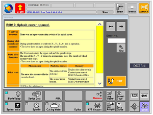
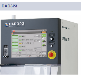
| Touch panel | A 15-type color LCD is employed to display alignment operation, cutting data, error messages, and other relevant information. It is also possible to operate the machine by directly touch the LCD. |
| Operation screens | Easy operation is realized by adopting GUI (Graphical User Interface). |
| Displayed guidance language | Can be selected from Japanese, English, Chinese (Simplified), or Chinese (Traditional). |
Additional information
| Manufacturer | Disco |
|---|---|
| Origin | USA |
| Type | Automatic |

